
The Supertron - A Tron With More Features
copyright 2001 by Scott Swartz, all rights reserved
Introduction
This article will describe an envelope controlled filter based upon the classic Mutron, but with expanded functions and controls including
-Six position frequency range selector
-Ratio, threshold, attack, and release controls for better control of dynamic response
-Full wave rectifier in the side chain for smoother filter sweep
-Circuit utilizes easy to source VTL5C3 Vactrol light dependent resistors (LDR), no magic 0805 component
-Effects loop so that original envelope is available to control filter at the same time the audio signal is processed with fuzz, etc.
For more extensive background on envelope follower, check out Mark Hammer's excellent article, "The Technology of Envelope Controlled Filters" at http://hammer.ampage.org/files/Autowah.PDF. I have incorporated some of the ideas that he discusses into this design.
State Variable Filter Circuit
The SVF topology used here is exactly the same as on the Mutron. This is a very common circuit, and probably every book of circuits has this one.
The only real addition is the 2P6T frequency range switch, which is nothing more than an expansion of the high/low swith found on the Mutron. This simple addition adds a huge amount of new sounds and allows adjustment of the sweep range to better complement a given guitar.
Side Chain Circuit
This is the key portion of any envelope follower, and the circuit used here is expanded greatly from the Mutron design for maximum flexibility.
The first addition is adjustable gain for the side chain, which provide a sensitivity control. This is interactive with the threshold control, as explained below. You may want to change the sensitivity control to a 1 meg pot for greater range if your guitar is really low output, for my guitars the 500K gave plenty of range.
After the side chain gain is set, the signal is sent through a full wave rectifier. This is an upgrade over the mutron half wave rectifier I highly recommend, as it only takes another 1/2 TL072 and a couple of other components.
After the rectification, the signal is routed to a threshold stage. This is a classic opamp differential amplifier, with a positive bias applied to the - input. A positive pulse from the rectifier that is larger than the bias setting will drive the output positive. The diode connected at the output is then forward biased and conducts the pulse forward since the cathode of the diode is at ground potential. A positive bias on the - input is required since the stage performs a subtraction, ie X (positive pulse at plus input) - Y (positive bias at minus input) = Z (output). Using real numbers, lets say X = +3 and Y =+1, the result is (+3) - (+1) = +2 output. There is a definite difference in filter response comparing no threshold/low sidechain gain (as with the mutron circuit) to a higher threshold and higher gain setting. In fact, I much prefer how the sweep interacts with the audio signal with some threshold dialed in. This design allows for both options.
The signal that passes through the diode is routed to the integrator, which converts the rectified signal to a smooth varying DC signal. Due to the full wave rectification used, the ripple frequency is twice the fundamental, which is very easy to integrate into a smooth varying DC signal. The capability for fast attack and release times and the elimination of filter modulation caused by ripple are the major advantages of the FWR design.
The signal from the integrator is routed to the drive direction opamp stage so that the filter can be swept either up or down in frequency. The design of this stage is taken directly from the mutron. In the upward drive position, the output of this stage is driven from 0 volts up to 1 volt in response to a signal of +1 volt from the integrator. In the downward drive position, the voltage on the output will be driven down from a adjustable static value by 1 volt in response to the same +1 volt signal from the integrator. The static value is made adjustable so the downward sweep can start at a different point than the upward sweep would stop at, if desired, or it can be adjusted to sweep the same range.
The output of the drive direction stage is routed to the LDR drivers, one for each LDR. These noninverting opamp stages have adjustable negative bias for the - input, which adjusts the static no signal resistance by raising the output voltage above ground. In addition, the resistance in series with the LED section of the LDR is made adjustable, which provides a "span" control for the amount the LDR resistance is swept with a given signal. The adjustments are somewhat interactive, but with both pots for each LDR, the upper and lower resistances can be matched closely without having to try a bunch of LDRs to find a matched pair.
This side chain circuit is also ideal for use in a LDR based compressor circuit. I have an early prototype of this idea and I plan to add an article about this to this site soon, watch for it.
Construction
This circuit is complex and requires a fairly large enclosure due to the 7 enclosure mounted controls, 6 dual opamps, the LDRs, and the power supply components. The best choice that is readily available is the Hammond 1590F, which is 7.4 x 7.4 x 2.2 inches. There is plent of room with this box, in fact you could probably fit a bunch more opamps in for other functions with the amount of board space available. With a PCB layout, it might be possible to fit everything into a Hammond 1590DD (4.7 x 7.4 1.3 inches), I am in the process of laying out a board with this as the target enclosure. Stay Tuned......
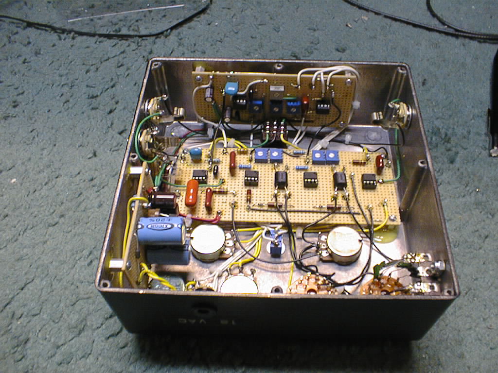
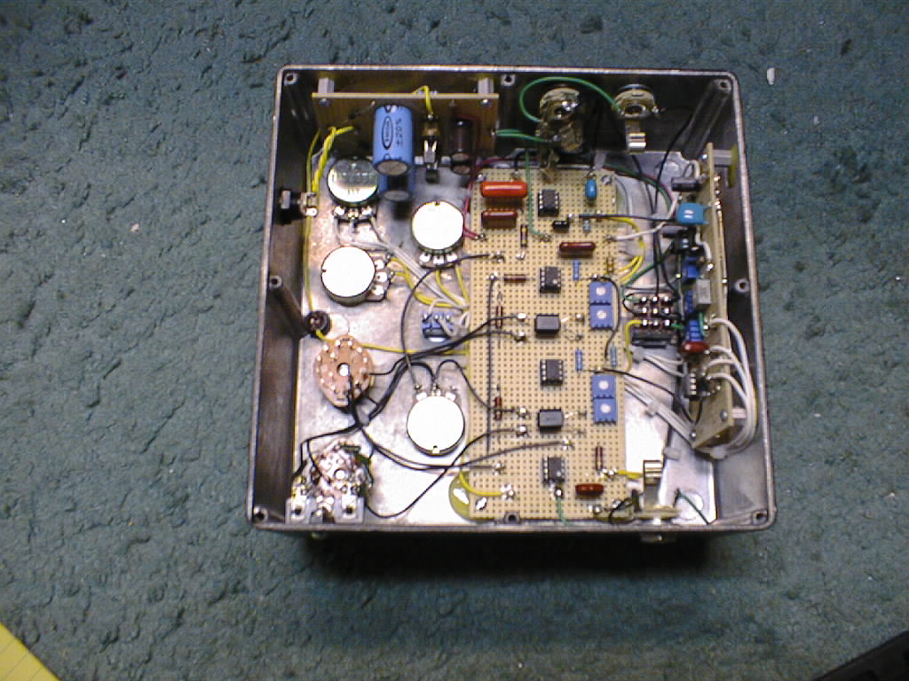
I constructed the circuit on three perfboards; One for the power supply (diodes, caps, and regulators), a side chain board with two opamps and associated components, and a main board with four opamps and the LDRs for the state variable filter, the LDR drivers, and the sensitivity and output gain stages. Wiring on perfboard takes a long time, but for making the first example of a design, it's probably more time efficient. Since the 1590F is quite deep, I was able to mount the power supply and side chain perfboards on the "side walls" of the enclosure, perpendicular to the top surface.
Startup
There is inevitably some tweaking required to get an envelope filter working right.
The first step is to verify correct operation of the power supply. Verify that the regulators are giving the correct +/- 12 volts, and if available use a scope to check for ripple. Use a 470 ohm 1 watt resistor shorted between each rail to ground to verify regulation with a load.
Next, verify that the side chain is working properly. The first step is to adjust the 500 ohm trim pot so when the threshold pot is at its minimum setting, the diode at the threshold opamp is just biased off, and the voltage on the cathode of this diode is at ground or very near to it. Using a signal generator, apply an audio signal of 1 volt rms and verify that a varying DC voltage is being created at node F. This is easiest to do with a scope, but if all you have is a DVM it should still be visible as the audio signal is applied. Verify that the Threshold control can reduce the varying DC generated and stop it completely at high settings.
Next, the upper and lower resistances of the LDRs need to be checked. To check the upper resistance, switch to upward drive. You can measure these resistances with the circuit powered up, just attach the DVM leads to the cell leads on the LDR. I set mine to read about 100K and 6K at the two extremes on both LDRs. With the 220K resistors in parallel across the LDR cells, the actual LDR resistance is about 180K and 7K. I recommend setting the span resistor pots to their midpoint and adjust the bias pots to give the 100K reading. These readings are a good starting point.
With the side chain known to be working and the LDRs set, the filter can now be checked out. If there is no sweeping of the filter, there is probably a wiring error in filter section. Check all three modes and verify that the six position range switch moves the sweep range up and down.
After correct operation is verified the trim pots can be adjusted to suit you tastes, specifically attack, release, LDR span, starting point of downward sweep, etc. This will take some experimentation.
There are a lot of sounds not available from the standard mutron circuit that this design allows for. For instance, the range switch can be set low with the sensitivity cranked up for a very wide sweep. There are lots of others, check it out.
Schematic and Photos
Here is the Schematic.
Here is Interior Photo 1.
Here is Interior Photo 2.
Here is a Photo Of The Top. Yes, its plain, but my recording gear can't tell how the box is painted.
Hear The Sound Files
Here are three MP3 files to give you an idea what it sounds like. With all the adjustable parameters, there are many other sounds that are possible, but these demonstrate the three major modes - lowpass, highpass, and bandpass. The recording signal chain is guitar amp to Sennheiser MD421 to homebrew tube mic preamp to mixer (EQ bypassed) to Tascam CD Burner. The stereo effects buss of the mixer was used to add a small amount of digital reverb, Small Chamber preset on a Digitech TSR-24.
Sound File 1 - Lowpass Filter Mode
This passage starts with a bit of single note lead playing, then rhythym chords through a 12 bar blues. The frequency range is set to a low setting for a wide sweep and the drive set for upward. The guitar is 62 Reissue Strat set for neck pickup only, played into a Twin Reverb type amp.
This is a rhythym riff with single notes and triads. The frequency range set to a low setting and the drive set for upward. This creates a "quack" type of sound. The guitar is 62 Reissue Strat set for neck pickup only, played into a Twin Reverb type amp.
This passage starts with some chords and then progresses to a single note riff. The frequency range is set to a high setting and the drive set for downward. This give the classis "chewy" sound, as heard on lots of funk records. The guitar is 62 Reissue Strat set for neck pickup only, played into a Twin Reverb type amp.
Back To
Projects